Key selection criteria when buying active harmonic filters
Active harmonic filters can effectively cancel harmonic distortions from the network. This blog post will explain the key criteria that should be kept in mind when buying an active harmonic filter.
1.1. Inverter topology
Most modern AHFs are built on a 3-level NPC inverter topology which brings several benefits compared to AHF’s built on the conventional 2-level topology. In a 3-level topology, the switching frequency and voltage stress are distributed among the IGBTs. Reduced stress extends the lifetime of the power electronics. 3-level NPC inverter produces an output waveform that is closer to sinusoidal, which enables a reduced physical size of the whole AHF system, due to the smaller LC-filter. Higher efficiency, lower losses, and lower noise levels are also achieved. These make the overall cost of ownership much lower.
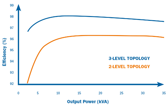
Fig. 1: Comparison of 3-level NPC inverter topology vs. 2-level
1.2. Losses
Depending on design and topology, AHFs can have higher or lower losses. Checking the losses is important as they will reduce the life cycle cost of the investment. Usually, AHF’s have about 2-3% losses (depending on rated power). AHF’s built on 3-level NPC inverter topology have lower losses than 2-level ones. Depending on the user profile, reduced losses create a potential for considerable financial savings if the LCC is calculated over a period of a few years.
1.3. Response time
Some power quality phenomena occur extremely fast, requiring the mitigation to be even faster. If the process is affected by fast voltage fluctuations or transients, it is very important to evaluate the AHF’s overall response time. Typical applications that require fast mitigation are for example welding machines, lifts, and cranes.
1.4. Interharmonics
Interharmonics are usually caused by synchronization issues. If the installation includes inter harmonic sources, the manufacturer should be consulted as not all AHFs can deal with this. It is a common issue with cyclo converters or some types of older wind turbine generators.
1.5. Harmonic compensation capacity
Harmonics can be seen in the odd and even orders. Common capacity for AHFs is 25th or 50th harmonic order. Sometimes there is a claim of being able to mitigate the 51st harmonic, which has little value as harmonic orders of 51st and above do not appear in electric power systems. An important issue is that the AHF can offer the possibility of selecting which harmonic order to compensate. For some devices, it is possible to select the whole harmonic spectrum (1st to 50th, odd and even), but for some others, only a few harmonic orders can be selected. Depending on the application, the capacity to compensate for a certain harmonic order is a critical issue affecting the whole system’s performance.
1.6. Electromagnetic compatibility (EMC)
In some countries, there are strict guidelines regarding the EMC. To be sure that the AHF is not causing interference it must be fitted with a properly designed EMC filter.
1.7. Derating according to harmonic order
The rating of an AHF is usually defined at nominal load (at 50/60Hz). As the AHF works further up the harmonics, its capacity compared to nominal starts to derate. For example, a derating of 50% at the 13th harmonic order means that a 100A AHF has only the capability to compensate 50A at the 13th harmonic order.
Derating is a matter of how robustly the AHF is designed. This capability is more dependent on the change rate of the current than just the frequency and magnitude of the current (all different frequencies, their magnitude, and phase have an effect). Because of this, a derating curve cannot show the capability of the AHF. The only way to verify the real compensating capability of a device is to check its di/dt capacity. This compensating capability is better in 3-level NPC inverter topology AHF’s compared to 2-level topology devices.
1.8. Physical footprint and modularity
Most suppliers offer several installation alternatives: Cubicle type, wall mount, or, loose modules that can be locally installed inside new or existing cubicles. Cubicle usually includes relays and a proper air circulation system and has a higher IP rating than loose modules. A modular AHF design allows customers to adapt to potential changes in future harmonic filtering and reactive power compensation needs. Modular design means that it is possible to add easily to the AHF’s capacity within the existing configuration, saving both costs and space.
1.9. Voltage
AHFs are offered in a range of voltages, the most common is 200V up to 690V. Some manufacturers can produce AHFs for even higher voltages, up to 1000V, without a step-up transformer, reducing costs and footprint. It is possible to connect AHFs to medium voltage systems using a suitable step-up transformer. Step-up (or step-down) transformers can reduce compensation performance due to increased impedance between the AHF and network.
1.10. HMI
There are different HMI setups for AHF’s. Some have a very simple front HMI while others include graphs showing the current and voltage waveforms and many further functions in different languages. A great added value is to have at least a web-based interface allowing in-depth monitoring and control functionality.
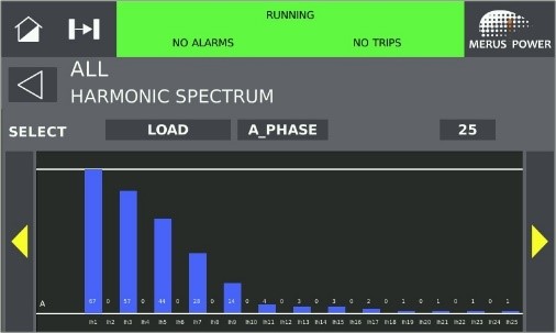
Fig. 2: Example of active harmonic filter’s HMI
1.11. Commissioning software
Commissioning and service of AHFs without proper tools can be time-consuming. Some suppliers provide software for this. The minimum required functionality should be that the system performs a self-check of voltage and CT phase order, CT polarity check, self-diagnosis, and self-calibration. Such features will find installation errors before they can cause problems and will shorten the commissioning time. If the AHF does not have this type of software the commissioning becomes more complex and might require external support adding to the system costs.
1.12. Smart Grid functionality
Some AHFs have a built-in power quality analyzer to calculate the required compensation. Some suppliers enable the user to connect all AHFs on-site through a web-based architecture. An operator can then have an overview of the status of all connected AHFs and log them. This enables the possibility to log events that could have caused production disturbances, monitor individual AHFs, and remote monitoring and analysis capability.
1.13. Control of detuned capacitor banks
Very often AHFs are installed at sites together with existing or new contactors or thyristor switched detuned capacitor banks. Some suppliers offer the possibility to control the steps of these banks directly from the AHF’s control system through dedicated digital outputs in the AHF. By doing this it is possible to use the comprehensive power quality monitoring and reporting features of AHFs to accurately monitor all the parameters of the installation and control the total power quality improvement needs. This brings optimal system integration, efficient operation, cost savings on the control system, and the possibility to build hybrid var compensators (HVC).
1.14. Cancellation of harmonics in neutral (4W)
Typically, active harmonic filters are installed to cancel harmonics distortions created by AC and DC drives or UPS systems. However, the use of LED lighting, as well as other single-phase loads in the buildings, also produces triple harmonics which accumulate in the neutral wire and should also be mitigated. High neutral wire currents can be a serious safety problem, as the neutral wire will heat up rapidly when overloaded. Therefore, the active harmonic filter should be easily configurable to 3W or 4W applications.